Rail to rail opamps can be regarded as two amplifiers. One of these amplifiers is ground (VSS) compatible while he other amplifier is supply compatible. The output signals of both amplifiers are added and buffered with an output stage. This is shown in the following conceptual drawing.
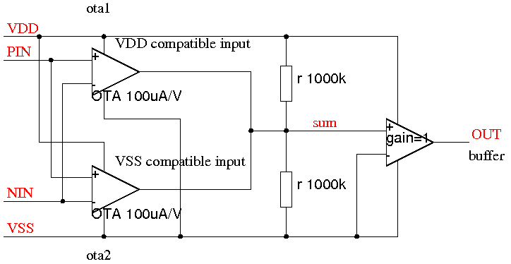
Fig. 1: Concept of a rail to rail amplifier
Typically the input stages are operational transconductance amplifiers. The signals are added adding the output currents. To make the input stage commom mode range wide enough the typical design is a folded cascode. The following example shows a PMOS input with NMOS folded cascode used for a ground VSS) compatible input.
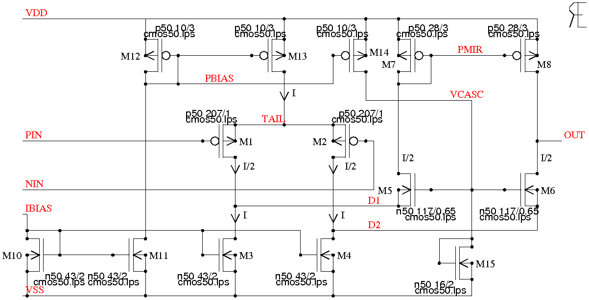
Fig. 2: Example of a simplified PMOS input stage with folded cascode
The offset of the amplifier depends on the matching of the transistors (M1, M2), (M3, M4), (M7, M8). Impact of early effect is neglected in this simplified example.
M1, M2 work as a classic differential amplifier. So there the offset simply calculates as:
Vos12 = Vostech / SQRT(W*L) (1)
Let us assume we have a Vostech of 15mVum (This is a typical value for 15nm gate oxide CMOS transistors in silicon technology) and W=207um, L=1um. We will get an offset contribution of M1, M2 of Vos12=1.0425mV
Assuming we work in strong inversion the gain of the OTA (oerational transconductance amplifier) will be:
gm = 2*2*Vgseff*kp'*W/L (2)
The second factor 2 is caused by the differential stage adding the currents again at the output.
Vgseff is the difference between the gate-source voltage of M1, M2 and the threshold. To calculate Vgseff we need the current of the two transistors. k' for normal silicon technologies can be estimated as:
kn' = 2000uAnm/(SQR(V)) / tox (for NMOS transistors) (3)
kp' = 700uAnm/(SQR(V)) / tox (for PMOS transistors) (4)
Vgseff = SQRT(I*L / 2*W*kp') (remember the transistor is working at I/2) (5)
Example: I=100uA, tox=15nm leading to k'=46.7uA/SQR(V), W=207um, L=1um leads to 72mV (well, not really strong inversion, but let us pretend it does not make too much difference). Plugging these 72mV into equation (2) we get a gm of 2.784mA/V (quite high! the truth will be lower because we used strong inversion assumption although M1 and M2 are already in the transitional area to weak inversion).
Next we have to look at the offset contribution of the current sinks. M3, M4 operate at current I. So we have to calculate Vgseff of M3 and M4, find out gm of M3 and M4 and calculate the current error caused by the possible offset of M3 and M4.
Vgseff34 = SQRT((I*L/(W*Kn')) (6)
Example: kn'=133uA/SQR(V), W=43um, L=2um, I=100uA leads to Vgseff34=187mV.
gm of the current mirror M3, M4 calculates as:
gm34=2*Vgseff34*Kn'*W/L (7)
Multiplying this gm34 with the offset of M3, M4 we get current error of the two current sinks. Ideally the offset voltage should be described in the technology manual. If not let us take typical values from literature. For most silicon technologies it is a reasonable assumption to expect 1mVum/nm * tox.
Ierr34 = gm34 *Vos34 (8)
Example: Vgseff34=187mV, W=43um, L=2um, Vostech=15mVum, kn'=133uA/SQRT(V) we get gm34=1.069mA/V, Vos34=1.617mV, Ierr=1.729uA.
The current error must be divided by the transconductance of the differential amplifier to calculate the offset contribution of the current sinks. Comming back to our example we had a gm of 2.784mA/V. So the offset contribution of the current sink becomes:
Vos34 = Ierr34/gm (9)
Example: Vos34 = 1.729uA/2.784mA/V = 0.621mV
The same calculation must be done for the current mirror M7, M8. The only difference compared to the sinks M3 and M4 is that transistors M7 and M8 operate at I/2. So equation (6) must slightly be modifed:
Vgseff78 = SQRT((0.5*I*L/(W*Kp')) (10)
gm78=2*Vgseff78*Kp'*W/L (11)
Example: I=100uA, L=3um, W=28um, Kp'=46.7uA/SQR(V) leads to Vgseff78=0.339V, gm78=295uA/V.
Again this gm has to be multiplied with the offset of the transistors using equation (8) and divided by the transconductance of the input transistors using equation (9)
Ierr78 = gm78 *Vos78 (12)
Vos78 = Ierr78/gm (13)
Example: gm78=295uA/V, Vos78=15mV/SQRT(28*3)=1.637mV leads to Ierr78=0.482uA and Vos78=0.17mV
Now the equations are known. So it is an easy thing to plug it all into a spread sheet.