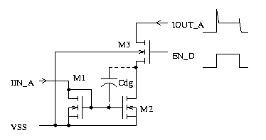
Fig. 1: switching a current generator with a MOS transistor.

Fig.
1: switching a current generator with a MOS transistor.
High
speed switching may suffer from overshots caused by the miller capacity
of M2. The significantly smaller spike at the end results from the gate-drain-capacity
of the switching transistor M3.
To
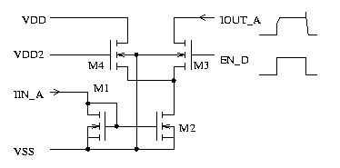
improve the performance the voltage swing at the drain of M2 must be reduced.
This leads to the following circuit:

Fig.
2: Reduction of the voltage swing at the drain of M2.
VDD2 is a reference voltage slightly lower than the high level of the control signal EN_D. What is left is the influence of the miller capacity of M3.
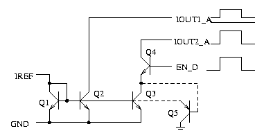
Using the simple concept of figure 1 for bipolar current switches will not work well. The parasitic PNP Q5 included in Q3 will sink most of the reference current IREF into the substrate while Q4 is off. So the current IOUT1_A will change as well depending on the state of the switch Q4.

Fig.
3: Inappropriate bipolar current switch.
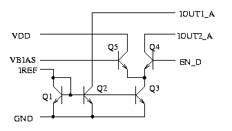
Bipolar current switching circuits MUST keep the current flowing to prevent saturation of the current generator. This is achieved in the following switch.

Fig.
4: Bipolar current switch with acceptable performance.
Emitter coupled logic is based on this kind of bipolar current switching.