RS 232 0-modem without galvanic
connection
(Last update May 13 2017)
A lot of
measurement hardware available can be connected to the computer using
an RS232C link. But it is not always desireable to establish a
connection between different power supply domains via the ground line
of the interface. (Imagine you wanted to measure signals tied to a DC
voltage differeing from the ground of your computer. This would
immediatelly lead to a current flow that in extreme cases may be
destructive for the PC or measurement systen!)
Even if there is no DC offset a ground loop could act as an antenna and
superimpose disturbance on the measurement carried out.
To avoid these problems an RS232C link without galvanic connection is
helpful.
Probably the most simple way of achieving this is using opto couplers.
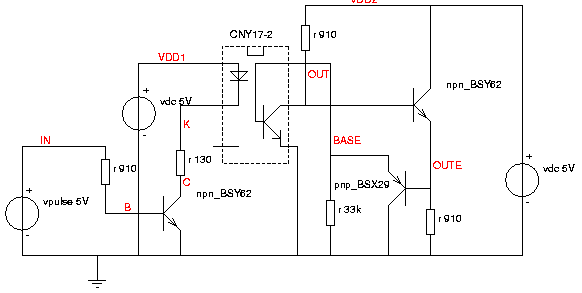
The following circuit displays the drive and receive circuit used.

Fig. 1: Single channel of the optical link
The pulse source on
the left drives the transistor npn_BSY62. The collector current is
limited by a 130 Ohm resistor. Current flow trough npn_BSY62 turns on
the light emitting diode (LED) inside the coupler CNY17.
The connection between the emitter of npn_BSY62 and the emitter of the
phototransistor inside the coupler can be removed to create a coupler
without galvanic connection. In the circuit above it is left
intentionally to have the same ground reference on both sides for
simulation.
Since the transistor inside the coupler is not optimized for saturated
switching like the BSY62 transistors it must be kept out of saturation.
Therefor the collector of the photo transistor is shifted down one VBE
by the rightmost transistor (npn_BSY62). The follower pnp_BSX29 pulls
down the base of the photo transistor before it reaches saturation.
The test circuit (for xcircuit schematic editor), a component library
and the SPICE netlist are also is available:
test_CNY.ps
(schematic for xcircuit editor)
test_CNY.spc (SPICE netlist)
system_lib.lps (a little
library including npn_BSY62, pnp_BSX29 and CNY17)
P0131_half_simu.ps (3
channel schematic for simulation)
netlist (netlist for the simulation
of P0131_half_simu.ps)
To make the netlist
and the library simulatable the files can simply be concatenated by
something like "cat system_lib.lps test_CNY.spc > test_CNY.cir" .
RS232C 0 modem
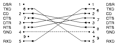
An RS232C 0
modem using 9 pin connectors looks like this:

Fig. 2: RS232C 0
modem pinout
The ground line is drawn dashed because this is the wire we will open.
In figure 3 we see 3 signals carying data in one direction plus 3
signal carrying data in the oposit direction. So we need a total of 6
channels.
With the symmetry we have we can build the circuit of two indentical
halfs.
One Half of
the circuit
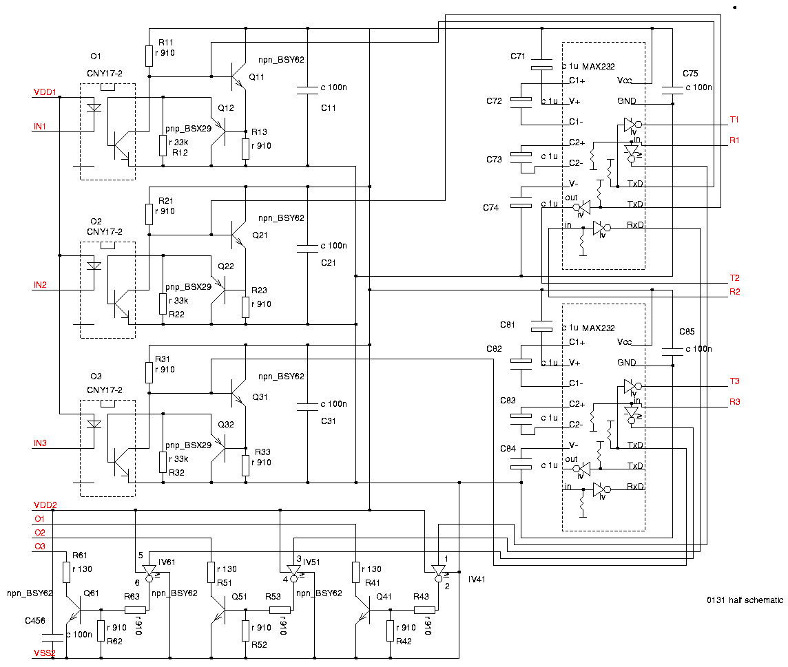
The
following diagram shows one half circuit.

Fig. 3: 0-model
half circuit
The circuit
consists of 3 channels of the circuit of figure 1, some inverters (IVx1
of a 74HC04) and two interface drivers (MAX232) changing the signal
levels to the standardized levels of an RS232C link.
RS232C 0
modem complete circuit
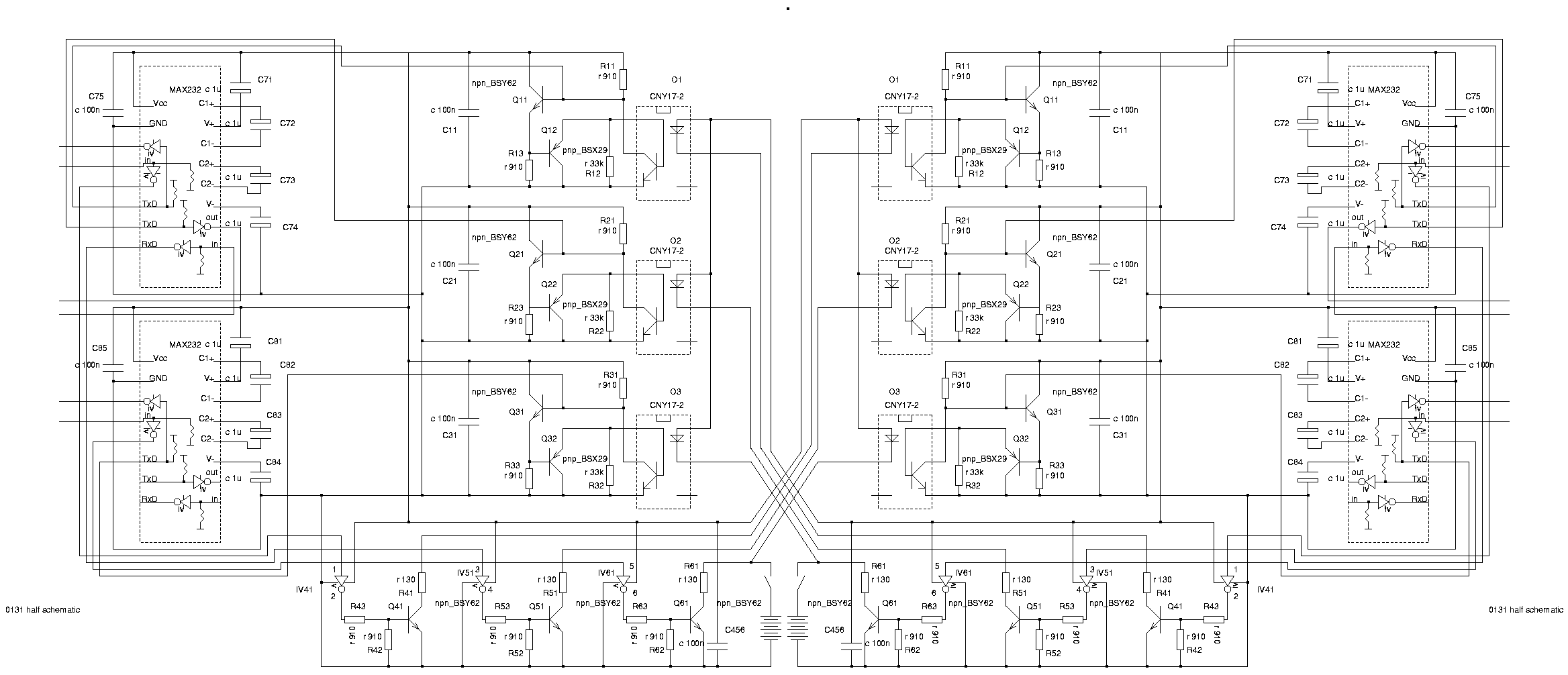
Two of the half
circuits shown above make the complete 0-modem:

Fig. 4: Complete
circuit
To make things
easier there also is a little description in pdf-format:
description.pdf
The
circuits of figure 3 and 4 are available for xcircuit too but since
there is no model for MAX232 they can nor be simulated.
P0131_half.ps (circuit of
figure 3)
P0131_both.ps (circuit of
figure 4)


